Bosch- G Series Setup Guide
The following guide provides steps to configure and initialize the G series panel in the Symphony AC Software. Use this guide as a quick reference. Please contact Senstar Corporation for questions. Considerations Prior to Setup The Mode, Bosch Firmware Version, and Symphony AC Software version will depend on the Bosch panel used. 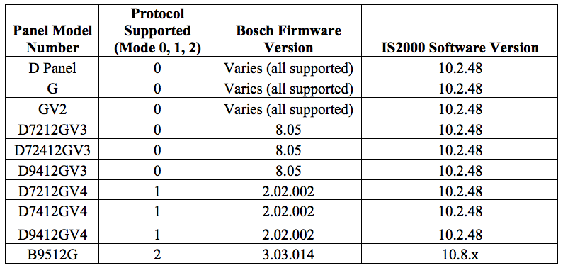 DX4020 vs. B420/B426: When setting up the Bosch GV panel, you must know the difference between the DX4020 and the B420/B426, as the steps will vary depending on which one you utilize. The differences between the DX4020 and the B420/B426 are as follows: DX4020:
 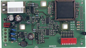 The Conettix DX4020 Ethernet Network Interface Module (Lantronix) creates two-way communications over Ethernet networks for compatible control panels. Typical uses include:
- Reporting to the Conettix D6600 Communications Receiver/Gateway
- Remote administration with Remote Programming Software (RPS) or RPS-Lite
- Connecting to a PC for programming with Symphony AC
Typically, you will find older systems using the DX4020 units such as G, GV2, and some GV3 panels. B420/B426: 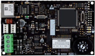 The B426 Conettix Ethernet Communication Module is a four-wire powered SDI, SDI2, and Option bus device that provides two-way communication with compatible control panels over IPv4 or IPv6 Ethernet networks. Typical uses include:
- Reporting and path supervision to a Conettix Communications Receiver/Gateway
- Remote administration and control with Remote Programming Software or A-Link
- Connection to building automation and integration applications such as Symphony AC
This device is capable of working as the gateway for all Bosch alarm panels (both legacy and current). This unit has replaced the DX4020 and B420. Note: If you are using the B426, you must first assign the IP address PRIOR to following the steps below. If you do not know or have not set the IP Address for the B426 Card, please see the following Bosch document for instructions: http://resource.boschsecurity.com/documents/B426_Installation_Guide_enUS_11017142667.pdf Symphony AC Alarm Licensing: Ensure that you have the proper Symphony AC door license if you wish to utilize alarm panels, including but not limited to Bosch panels. Senstar licenses Symphony AC based on the number of doors. For sites that use alarm panels, you will need to purchase the corresponding door license. Please refer to the table below and contact Senstar Corporation (sales@Senstar.com) if you need to upgrade your existing door license. 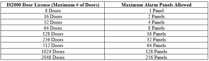 Estimated Import/Download Times When importing and downloading to the various Bosch panels, the download times may vary depending on the mode of the panel you are using. The mode of the panel depends on the model of your panel (please see the chart above for the panel models and corresponding Modes). Please refer to the chart below for a general list of import/download times.
 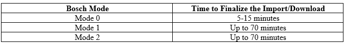 Note: On a download all from the Symphony AC software, the panel might become non-responsive as the download or import is in progress. Setting Up the Bosch G Series I. Connect the GV Panel to the Network. Note: For all network modules (B426, B420, and DX 4020), the power comes from the SDI bus of the Bosch panel. Typically, the Bosch panel is wired to a power supply transformer. II. Accessing the Network Page of the Bosch GV Panel
- Power on the Bosch GV Panel. Make sure that the Network Gateway (DX 4020, B420, or B426) is wired to the SDI 1 peripheral device connector.
If you are using the DX4020 Gateway: Flip DIP Switches 1, 2, 3, 4, 5, 6, and 8 to the ON position (Down) and DIP switch 7 to the OFF position (Up). Re-apply power to the controller. If you are using the B420 or B426 Network Module: Ensure that the rotary dialer is pointing to the “3”. Re-apply power to the controller.
- Perform a direct connect to the controller via cross-over and a PC/Laptop.
A. DX4020 Gateway If you are using the DX4020 Gateway, follow the steps below. If you are using the B420 or B426 Gateway, go to section B.
- Configuration of the network settings is done through the Lantronix Device Installer tool. Telnet needs to be enabled for the PC/Laptop. Run the Lantronix Device installer application to auto scan for DX4020 devices on the LAN. (See Figure 1)
Figure 1 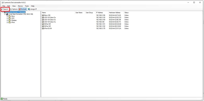
- Ensure that the Xport-03/04 device is selected and then click on “Assign IP”. (See Figure 2)
Figure 2 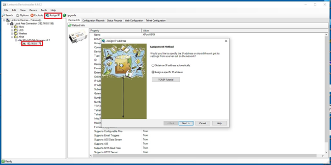
- You will be asked if you wish to specify the IP address or if the unit should get its settings from a server out on the network. (See Figure 3)
Figure 3 
- Select “Assign a specific IP address” and click “Next”. (see Figure 4)
Figure 4 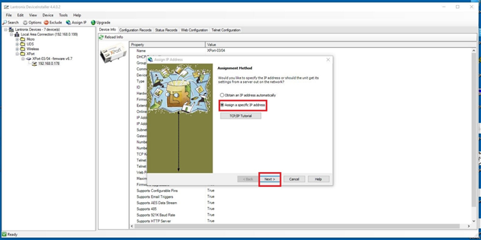
- Type in the IP address, subnet, and default gateway, and click “Next”. (See Figure 5)
Figure 5 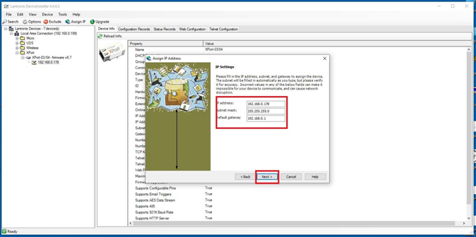
- Click “Assign”. (See Figure 6)
Figure 6 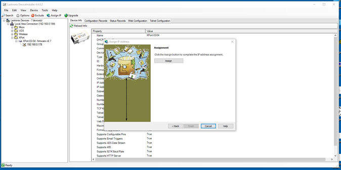
- Once the assignment is finished, click “Finish”. (see Figure 7)
Figure 7 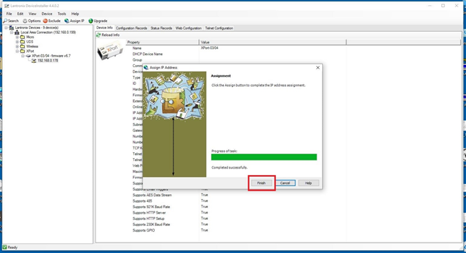
- Next, re-discover the DX4020 device and make sure the unit is selected. Click on “Telnet Configuration” and click on “Connect”. (See Figure 8)
Figure 8 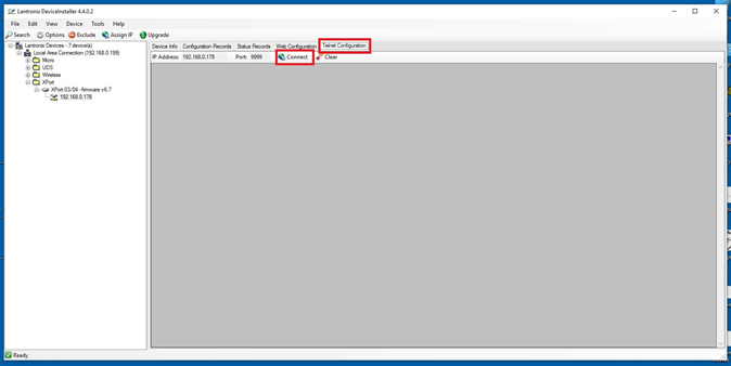
- Press the “Enter” key (on your keyboard) followed by “1” for “Your Choice?” and then press the “Enter” key (on your keyboard). (See Figure 9)
Figure 9 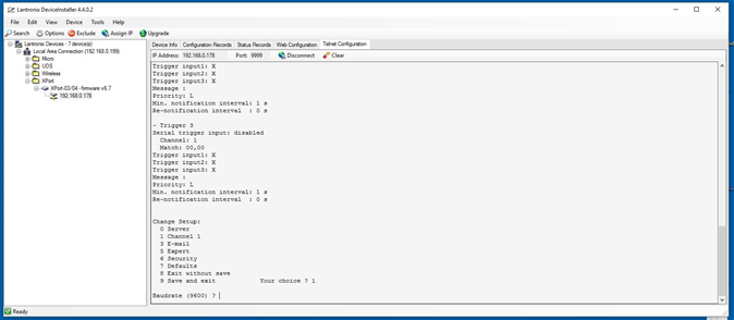
- Set the following parameters. Unless mentioned below, the other settings shall be kept as default.
- Baudrate: “9600”
- I/F Mode: “4C”
- Flow: “00”
- Port No: “3001”
- ConnectMode: “C0”
Press the “Enter” key until you get to the last menu. Press “9” followed by “Enter” on your keyboard to save and exit. (See Figure 10) Figure 10 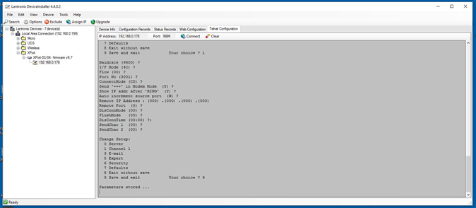
- Double Click on the Xport-03/04 Device to access the Network and Configuration Options. (See Figure 11)
Figure 11 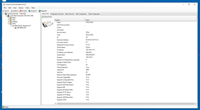 B. B420/B426 Gateway If you are using the B420 or B426 Gateway, follow the steps below. If you used the DX4020 Gateway, please skip this section and go to section III.
- Configuration of the network settings are completed by connecting to the device using a web browser. This device can be auto discovered by Symphony AC on the LAN.
- Open a web browser and type the IP address to access the network and device settings. Type the Password: “B42V2” and click “Login”. (see Figure 12)
Figure 12 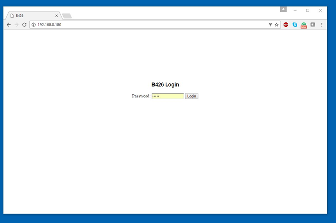
- Once logged in, click on “Basic Network Settings” and enter the IP Address, Subnet, and Gateway. Ensure that the TCP/UDP Port number is set to 3001. Set the Legacy TCP automation to “Yes” to enable it. Click “OK” and “Save and Execute” to save the changes. (See Figure 13)
Figure 13 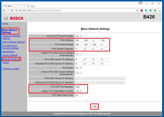 III. Setting Up the Bosch G Series Within Symphony AC
- Launch Symphony AC and navigate to the Hardware Manager module. Unlock the module by clicking the lock in the command toolbar. Right click in the hardware tree and select “Edit” to display the “Add Driver” command from the popup menu. Click on “Add Driver” to view the “Add a New Driver” popup menu.
- From the “New Driver” popup menu, click on the “Alarm System Drivers” category. Select the “Bosch G/B Series Alarm” driver. Click the OK
- Select the Bosch driver. Configure the Proper Protocol in the properties window as follows
For Legacy Bosch Panels (GV, GV2, and GV3), select the “Legacy” Protocol. For GV4 panels, select “Mode 1” Protocol. Note: Make sure to keep Legacy and Mode 1 panels on their own driver. DO NOT place Legacy and Mode 1 controllers under the same Bosch driver.
- Select the Bosch driver from the hardware tree and right click on it to bring up the popup menu. Select “Edit” and then “Add Controller.”
- There are two ways to add a controller. Controller(s) can be added manually one at a time or you can scan the network and add controllers.
a. To scan the network to add controllers, use auto setup and check the box next to the controller with the proper IP address that you wish to add.
- Note: More than one controller can be added simultaneously using the Auto Setup tool.
- Note: If using the auto setup tool, controllers can be viewed in the auto setup tool if they are in the same subnet. If you scan for the controllers with the auto setup tool but cannot see the controller, it is likely that the controller’s IP address is set out of the server’s reach because they are not on the same subnet. If this is the case, you will have to add the controller manually.
OR In the alternative, you can manually add controllers by using the manual setup. Select the controller type (here, the appropriate Bosch controller from the drop down menu). Select the Controller Address from the drop down menu and the Controller Group from the drop down menu. b. Click the “OK” button below to continue.
- Set the “Service username” and “Service Password” for the Driver. This is typically a local Windows user account that will be used to run the driver as a Windows Service. Click Save.
Note: The “Service User” needs to have rights to run Windows services. Usually, an Admin account will have the rights. If using a domain account, enter the full name. In the example below, the full name would be: (.\Abdul). The domain is set by the IT administrator or the administrator of the local account.
- Starting the driver:
Select the Driver in the hardware tree, right click on the driver, and select the “Start Driver” item from the “Driver Commands” menu.
- Once the driver starts, a green box showing “BOS” will appear in the Information Window in the top right of the application. The Driver Status Screen should display “Running” in a green box along with the Time Date of the Driver, the Driver Version, and the Firmware Version. When selected, the Bosch panel should show a Online status in the top right (as indicated by the green “BOS” box).
- Select the Controller and ensure that the Firmware Version is displayed in the controller status screen to indicate that the Bosch panel is online. Right click on the Controller and select “Controller Command” and click on “Import Utility”.
- In the Import Utility, make sure that all databases are selected and click on “Begin Import”.
Note: This process can take anywhere from 5 to 15 minutes on the Legacy panels and 45 to 60 minutes on the GV4 panels to complete. During this process, the Bosch panel will not report any alarms/events.
- Once all the databases are imported, you can close the Import Utility.
- Expand the hardware tree and select each device to set properties. Make sure to enable each point to start getting the status. The Controller Status Screen should appear with a green “ONLINE” status.
- If a reader Module is part of the Bosch panel, make sure this is enabled under the properties of the hardware tree. Right click on a reader to test out Unlock/Lock commands. Events will now appear in real-time on the Event Manager.
IV. Adding Additional Bosch Panels If you wish to add additional Bosch panels, the process is the same. The following example will demonstrate how to add an additional Bosch GV4 panel. Note: You MUST keep each panel in its own controller group (i.e. one panel per controller group).
- Ensure that you add a second Bosch Driver.
Note: You can only add one driver per hardware type. If you need two different Bosch panels (for example, one GV4 panel and one GV3 panel), you must change the computer name before you can add the same driver. For example, if your computer name is “COMPUTER-PC”, you will need to change the computer name for the second driver to a different name, such as “COMPUTER-PC1”. Once the second driver is added, you can change your computer name back to the original computer name (here, change “COMPUTER-PC1” back to “COMPUTER-PC”). You will then have two working drivers for the same hardware type (i.e. One GV4 panel under one driver and one GV3 panel under a separate driver in the example here).
- Select the Bosch Driver and set the “Protocol” property to “Mode 1”. Click Save and start the Bosch driver.
Note: The mode may change depending on which drivers you wish to use based on the various Bosch panels. For the legacy Bosch panels, use Mode 0. For the Bosch GV4 panel, use Mode 1. For newer Bosch panels such as the B9512G, use Mode 2.
- Auto Scan the LAN for GV4 panels. Select the correct GV4 panel and click “OK”.
Note: The B420 and B426 network cards will auto discover as a “Bosch” LAN controller. Note: You CANNOT add GV4 Bosch panels in the same Controller Group/Driver as the GV, GV2, and GV3 Legacy panels. Note: Adding each Bosch panel on its own Controller Group is how the Database of each panel is preserved as an independent unit.
- Select the Controller and make sure that the firmware version is displayed in the controller status screen to indicate that the Bosch panel is online.
Note: Ensure that the firmware on the panel is at least firmware version 2.02.002 (Mode 1). Click on the Controller and select “Import Utility” from the menu. Note: The import can take 45 to 60 minutes.
- Test your points. Events will now appear in real-time in the Event Manager.