Axis A1001- Door Properties
Below is a list of door properties when using the Axis A1001 in Symphony AC. These properties can only be viewed once the module is unlocked, as shown below.
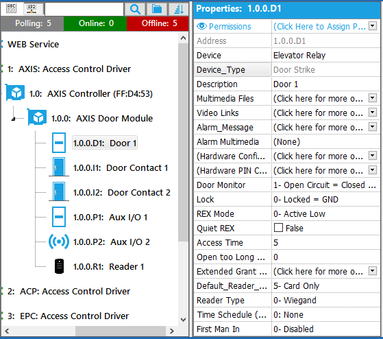
Address
The physical address of the door contact is automatically assigned within the Access Control Security Application. If the reader module has two (2) readers, the addressing for the door contact will be l1 for reader one and l2 for reader two.
Device
This property contains the different relay outputs. Options include: Control Point, Door Lock, Door Sounder, Door Strike, Elevator Relay, Light, and Speaker.
Device_Type
This is the device type for the device in use and cannot be modified.
Description
A description of the device, used to easily identify the location or function of the device. The description will display on Event Manager any time an event occurs at that point.
Multimedia Files
Video / Media that can be associated to the device and called up by right-mouse clicking on the events related to this device. To associate a Multimedia File, click on the drop down arrow to the right of the Multimedia File tag. Click the plus sign to add a new multimedia file. Click on the field to the right of “Description” to add a description. Click the drop down arrow to the right of the Multimedia tag and browse to the location of the saved multimedia file.
Video Links
Associate a camera to certain events of this device. Used to setup recording on a particular camera during particular event(s). Please note that the Access Control Security software must be licensed for the video module in order to utilize this feature. The camera must be previously configured for use in the system before the camera can be assigned to a point. For video configuration options, please see help section Video Configuration. To associate a video link to the door contact, click on the drop down arrow to the right of the Video Links tag. Click on the drop down arrow to the right of the Camera Address tag and select the camera to be associated to the point. Please note that the use of video by event is only available for certain manufacturers. If the model used does not support this functionality, the camera will display for all events. Contact Technical Support for information regarding what manufacturers this is available for.
Alarm_Message
A text field that is associated to the device when it goes into alarm state. This text field should be informative in describing what type of alarm has occurred. To create an Alarm message, click on the drop down arrow to the right of the Alarm_Message tag. Type the custom message in the text field provided. Click the green check mark to save changes. To exit without saving click on the blue x.
Alarm Multimedia
The sound that will occur when the alarm goes into an alarm state. Note: this feature requires the use of a sound card and speaker installed on the computer. To select the Alarm_Multimedia for the device, click on the drop down arrow to the right of the Alarm_Multimedia tag and select a wave file.
(Hardware Configuration)
This property will direct users to Axis’s entry manager. IMPORTANT NOTE: This page should only be used to verify if the door properties are updating accordingly. NO configuration should be done on this page.
(Hardware Pin Chart)
The hardware pin chart property shows in a diagram form how an A1001 panel is setup. For example, if a user has Two doors & Two readers, the diagram will display a Two doors & Two readers set up.
Door Monitor
Open Circuit = Open Door means that the door monitor will signal that the door is open when the circuit is open. Closed Circuit = Open Door means that the door monitor will signal that the door is open when the circuit is closed.
Lock
Locked = GND is for locks that remain locked during power outages (fail close/secure). Locked = 12 V is for locks that unlock during power outages (fail open/safe).
REX Mode
Active Low is if activating the REX (Request for Exit) device closes the circuit. Active High is if activating the REX device opens the circuit.
Quiet Rex
True means does not activate the door relay. False means does activate the door relay.
Access Time
The number of seconds the door shall remain unlocked after access has been granted.
Open too Long Time
The number of seconds the door is allowed to stay open. If the door is still open when the Open too Long Time has been reached, the Door Held Open alarm is triggered.
Pre-Alarm Time
A pre-alarm is a warning signal that is triggered before the Open too Long Time has been reached. Set the number of seconds before the Door Held Open alarm is triggered the system shall give the pre-alarm warning signal. If there is a reader with a beeper, the beeper will send the warning signal as a sound. To disable the pre-alarm, set the Pre-Alarm Time to 0.
Extended Grant Time Settings
Here, you can set the extended grant time settings, including the Pre-Alarm Time for Door Held Open, Extended Door Strike Time, and Extended Held Open Time.
Default_Reader_Mode
1- Disabled means no cards will grant access. 2- Unlocked means door strike disengages & reader unlocks 3- Locked (No Access, Allow REX) means no access and Request for Exit is allowed. 5- Card Only means only cards and key fobs will grant access. 6- Pin Only means only pins will grant access. 7- Card and Pin means cards/fobs & pin are required to unlock the door. 8- Card or Pin means the door can be unlocked with cards/fobs or a pin. 9- Disabled + means the reader mode is disabled, but VIP users with the VIP flag with a PIN & card can still gain access.
Reader Type
0-Wiegand is a reader type commonly used to connect a card swipe mechanism to the rest of an electronic entry system. 1- OSDP – Half Duplex is a reader type with two clearly defined paths/channels, and each party can communicate with the other but not simultaneously. 2- HADP – Half Duplex is a reader type with two clearly defined paths/channels, and each party can communicate with the other but not simultaneously. 3- OSDP – Full Duplex is a reader type that allows both parties to communicate with each other simultaneously. 4- HADP – Full Duplex is a reader type that allows both parties to communicate with each other simultaneously.
Time Schedule (Unlock)
The Time Schedule property allows users to set doors to be unlocked during a certain time frame. For example, if a user wanted to have the front doors unlocked from 9 a.m. to 5 p.m. (normal business hours), this would be set to unlock from 9 a.m. to 5 p.m.
First Man In
These properties allow you to enable and disable first man in. 0-Disabled First man in is not enabled. 1-First Man In (1 Reader) Reader 1 will act as the IN & OUT reader. 2-First Man In (2 Readers) Reader 1 is the IN reader & reader 2 is the OUT reader.