Elk- M1 Gold Controller Setup Guide
The following guide provides steps to configure and initialize the Elk M1 Gold controller panel in the Symphony AC Software. Use this guide as a quick reference. Please contact Senstar Corporation for questions. Considerations Prior to Setup Senstar does not recommend polling more than 32 ELK panels/controllers per driver. If you wish to poll more than 32 Elk panels/controllers, please add another Elk driver on another PC.Symphony AC Alarm Licensing: Ensure that you have the proper Symphony AC door license if you wish to utilize alarm panels, including but not limited to Elk panels. Senstar licenses Symphony AC based on the number of doors. For sites that use alarm panels, you will need to purchase the corresponding door license. Please refer to the table below and contact Senstar Corporation (sales@Senstar.com) if you need to upgrade your existing door license. 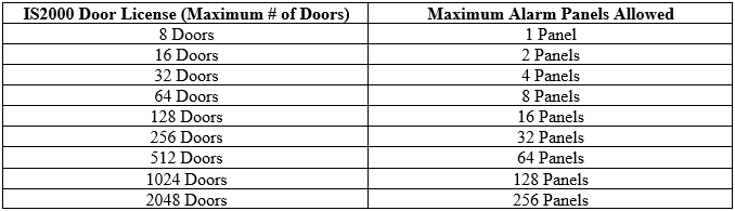 Setting Up the Elk M1 Gold Controller I. Accessing the Network Configuration Page of the Elk Panel Please ensure the following are set up with your Elk panel before configuring the Elk panel within Symphony AC:
- The Elk panel is connected to the Network via the ELK M1XEP
- The Elk M1 panel is powered up
- The Serial cable is connected from the Elk M1 to the M1XEP Ethernet module
- A network cable is connected from the M1XEP to your LAN (Router, Switch, or Hub) and ensure your PC/Laptop is also connected to the same LAN
- The M1XEP Ethernet module is powered on
- Ensure that the IP address has been updated in the System URL/IP field.
- Ensure that you have a successful connection and the bottom right of the screen displays a “Connected” status with a green circle.
- For a tutorial on how to configure the M1XEP module, please see the following link: https://www.youtube.com/watch?v=5nAFXdsmO_U
- Ensure that the following Globals are set to True within the RP software: G36, G37, G38, G39, G40, G41. Ensure that each Global is check marked.
- You have programmed the Master User and password in the RP software to access the Elk M1. (Note: The “Code” field indicates the password.)
II. Setting Up the Elk M1 Gold Controller in Symphony AC
- Launch Symphony AC and navigate to the Hardware Manager module. Unlock the module by clicking the lock in the command toolbar. Right click in the hardware tree and select “Edit” to display the “Add Driver” command from the popup menu. Click on “Add Driver” to view the “Add a New Driver” popup menu. (See Figure 1)
Figure 1: 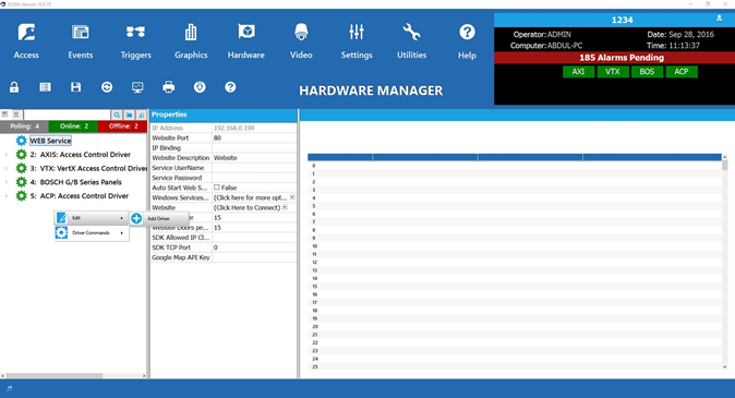
- From the “New Driver” popup menu, click on the “Alarm System Drivers” category. Select the “Elk Alarm System” driver. Click the OK (See Figure 2)
Figure 2: 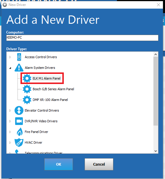
- Set the “Service username” and “Service Password” for the Driver. This is typically a local Windows user account that will be used to run the driver as a Windows Service. Click Save. (See Figure 3)
Note: The “Service User” needs to have rights to run Windows services. Usually, an Admin account will have the rights. If using a domain account, enter the full name. In the example below, the full name would be: (DOMAINNAME\Abdul).
Figure 3: 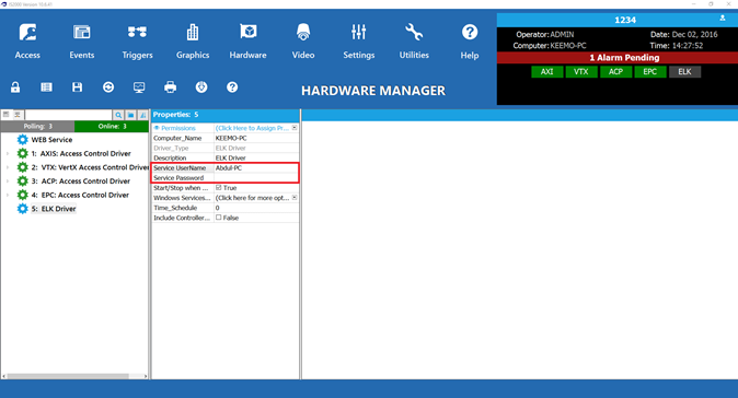
- Starting the Driver:
Select the Elk Driver in the hardware tree, right click on the driver, and select the “Start Driver” item from the “Driver Commands” menu. (See Figure 4) Figure 4: 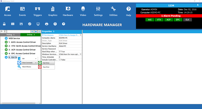
- Once the driver starts, a green box showing “ELK” will appear in the information window in the top right. The Driver Status Screen should display “Running” in green along with the Time Date of the Driver, the Driver version, and the DLL Version. (See Figure 5)
Figure 5: 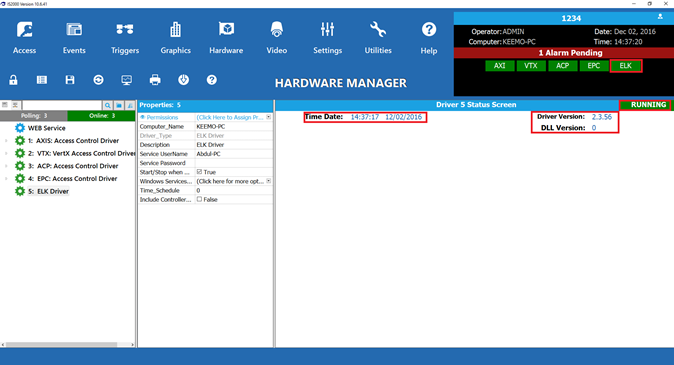
- Select the Elk driver from the hardware tree. Right click on the driver to bring up the popup menu. Select “Edit” and then “Add Controller.” (See Figure 6)
Figure 6: 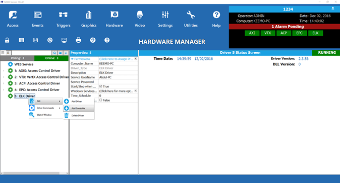
- There are two ways to add a controller. Controller(s) can be added manually one at a time or you can scan the network and add controllers.
- To scan the network to add controllers, use auto setup and check the box next to the controller with the proper IP address that you wish to add.
- (Note: More than one controller can be added simultaneously using the Auto Setup tool.)
- (Note: if using the auto setup tool, controllers can be viewed in the auto setup tool if they are in the same subnet. If you scan for the controllers with the auto setup tool but cannot see the controller, it is likely that the controller's IP address is set out of the server's reach because they are not on the same subnet. If this is the case, you will have to add the controller manually.)
- In the alternative, you can manually add controllers by using the manual setup. Select the controller type (here, the Elk controller). Select the Controller Address from the drop down menu and the Controller Group from the drop down menu.
Click the “OK” button below to continue. (See Figure 7) Figure 7: 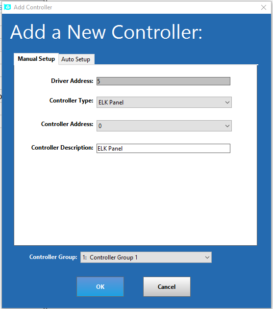
- If you added the controller by the auto setup tool, the controller should come online.
- If you did not add the controller by the auto setup tool, you will need to manually change the controller’s properties as follows.
First, unlock the module. (See Figure 8) Figure 8: 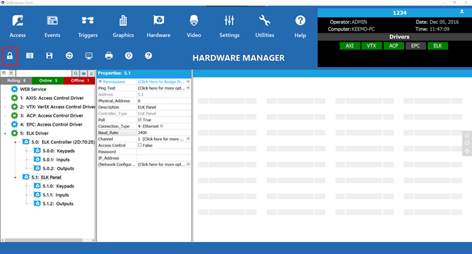 Select the controller to see the Properties. (See Figure 9) Figure 9:
 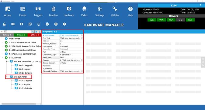 Type in the IP address and password. Ensure that the password used is the Master Password to ensure that you will have access to all viewing and setup of the Elk panel. Set the Baud Rate to 115200. (see Figure 10) Note: If you added the controller using the auto setup tool, you will NOT need to manually add the IP address, as the IP address is automatically added if the auto setup tool is used. However, you MUST still add the password. Figure 10:
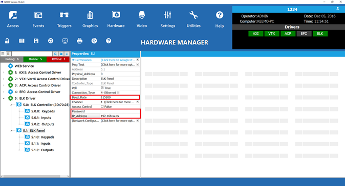
- Next, you will need to import the point descriptions and live statuses of all connected hardware. To do this, ensure that the module is unlocked in the Hardware Manager. Select the controller. Right click on the controller and select “Controller Commands” and select “Import Utility.” (See Figure 11)
Note: Before importing the point descriptions and live statuses of all connected hardware, you MUST ensure that the Elk Panel is online. If you do not have the Elk Panel online, the import command will not work.
Figure 11: 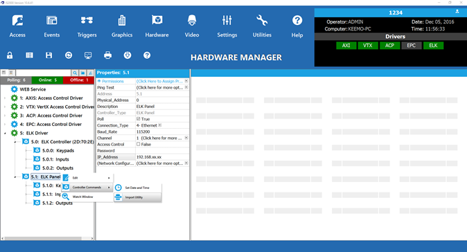
- Expand the hardware tree and select each device to set properties. Click on the Save command from the command toolbar. Double check that your controller is online, as indicated by the green “ONLINE” status on the controller status screen. (See Figure 12)
Note: It is always important to save any changes made to the properties of any device within Symphony AC.
Figure 12: 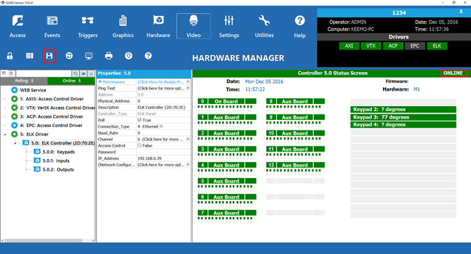
- Events will now appear in real-time on the Event Manager. (See Figure 13)
Figure 13: 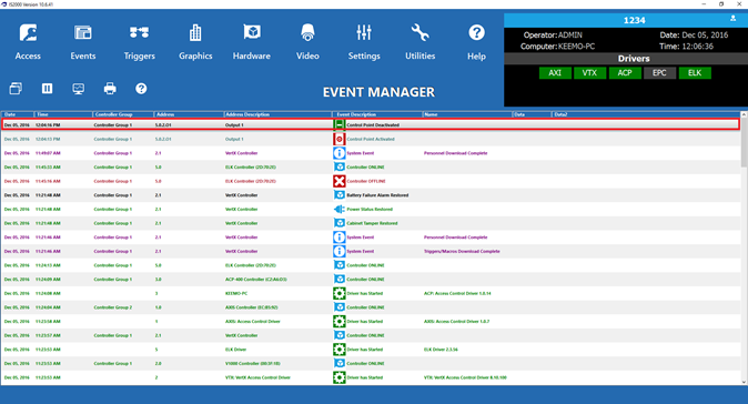 III. Elk M1 Gold Supported Features Below is a list of supported features for the Elk M1 Gold controller. Supported features include:
- Virtually unlimited number of users (host dependent)
- Arm/Disarm of Areas
- Activate/Deactivate Outputs
- Real-time status of outputs/inputs using Point Status
- Cross platform activation using the Aero hardware platform and Triggers/Macros
- Graphic Maps: including
- Arm/Disarm areas from graphic maps
- Activate/Deactivate outputs from graphic maps
- Area status indication by keypad from graphic maps (Armed, Disarmed, Not Ready)
- ELK Automation between Aero readers. A valid card read from a Aero reader will automatically disarm the ELK areas associated with that reader.