ZK Access- ACP-inBio Controller Setup Guide
Considerations Prior to Setup Please note the following considerations prior to setting up your ACP or inBio controller. Firmware Requirements: For ACP controllers, the firmware required is 4.1.9. For inBio controllers, the firmware required is 5.0.9. SQL Server Requirement: Please ensure that you are using Microsoft SQL Server version 2008 or later (any suite). Make sure the clients are connected to the SQL server. Setting Up the ACP/InBio Controller I. Connecting the Controller Connect the controller to the Network via Local Area Network (LAN) or directly connect with a crossover cable. Note: You must use the AC Adapter. II. Network Setup A. Using the ACP/inBio Discovery Tool First, you must set up the network using the ACP/inBIO Discovery Tool. This tool will scan the network and display the following:
- MAC ID and IP Address of each controller
- Subnet
- Default Gateway
- Firmware Version
- Install the ACP/inBio Discovery Tool.
Note: The tool can be downloaded from the Downloads section located under the support menu at http://Senstar.com/Symphony AC while logged in as a registered dealer. In the alternative, the tool can be requested by emailing support@Senstar.com.
- Once you have located the ACP/inBio Discovery Tool, save the file. Locate the file and click to open the file and click “Run” to install.
- Once you have begun to run the ACP/inBio Discovery Tool, click “Begin Auto Scan”.
- From the list, click on the controller you wish to program and enter the proper IP Address, Subnet, and Default Gateway. Confirm by clicking “Modify IP”.
- Once the IP address is successfully programed, a popup window will display to confirm as such.
III. Setting Up the ACP/inBio Controller Within Symphony AC
- Launch Symphony AC and navigate to the Hardware Manager module. Unlock the module by clicking the lock in the command toolbar. Right click in the hardware tree and select “Edit” to display the “Add Driver” command from the popup menu. Click on “Add Driver” to view the “Add a New Driver” popup menu.
- From the “New Driver” popup menu, click on the “Access Control Drivers” category. Select the “ACP Access Control” driver. Click the OK button.
Note: You should select the “ACP Access Control” driver regardless of whether you are adding a ACP or inBio controller within Symphony AC. The following steps are the same, regardless of whether you are adding a ACP or inBio controller.
- Set the “Service username” and “Service Password” for the Driver. This is typically a local Windows user account that will be used to run the driver as a Windows Service. Click Save.
Note: The “Service User” needs to have rights to run Windows services. Usually, an Admin account will have the rights. If using a domain account, enter the full name. In the example below, the full name would be: (Senstar\admin).
- Start the Driver: Select the “ACP: Access Control Driver” from the hardware tree. Right click and select “Driver Commands” and then click “Start Driver”.
- Once the driver starts, a green “ACP” box will show in the information window in the top right. The Driver Status Screen should display “RUNNING” in green, the Time Date of the driver, and the Driver Version.
- Select the ACP driver from the hardware tree and right click on it to bring up the popup menu. Select “Edit” and then “Add Controller.”
- 7. There are two ways to add a controller. Controller(s) can be added manually one at a time or you can scan the network and add controllers.
To scan the network to add controllers, use auto setup and check the box next to the controller with the proper IP address that you wish to add. Note: More than one controller can be added simultaneously using the Auto Setup tool. Note: If using the auto setup tool, controllers can be viewed in the auto setup tool if they are in the same subnet. If you scan for the controllers with the auto setup tool but cannot see the controller, it is likely that the controller's IP address is set out of the server's reach because they are not on the same subnet. If this is the case, you will have to add the controller manually. OR In the alternative, you can manually add controllers by using the manual setup. Select the controller type (here, the appropriate ACP or inBio controller). Select the Controller Address from the drop down menu and the Controller Group from the drop down menu. Note: If adding controllers manually, please ensure that you select the proper controller model and address. You can also add a controller description and select a controller group. Ensure that you have the last 6 digits of the MAC address BEFORE attempting to add the controller manually. MAC addresses should be typed in the following format: XX:XX:XX Click the “OK” button below to continue.
- In Hardware Manager, unlock the module by clicking on the lock/unlock command. Select the controller to see the controller’s properties. Click on “Communication Settings” to bring up the Communication Settings window.
- Type in the IP address, Subnet, and Default gateway. Click “OK”.
Note: This information is the same information you used to program the network settings via the ACP/inBio Discovery Tool.
- The controller will show as online in the controller status screen.
- Once you are ready to download to the controller(s), click on the Download button located on the command toolbar to view the Download Manager. Select the ACP or inBio controller(s) to download to and make sure the Database items are also checked. Click “Begin Download” to initiate a download to the selected controller(s).
- Expand the hardware tree and select each device to set properties. Click on the Save command from the command toolbar.
- The Controller Status screen should display a green “ONLINE” status.
- To test a reader with unlock and lock commands, right click on the reader. Click “Door Strike Commands” and select “Unlock Door”, “Lock Door”, or “Momentarily Unlock Door”. Events will now appear in real-time in the Event Manager.
IV. Controller Properties for the ACP/inBio Hardware in Symphony AC’s Hardware Manager Each hardware device has its own set of properties that can be configured to allow the operator to customize the hardware to meet their needs. The default TCP Port for the controller’s communication to the Symphony AC driver is 4370.
- From the Hardware Manager, click on the pad lock to unlock the Hardware module, without the pad lock unlocked; the controller properties box will not be displayed.
- Highlight the controller from the hardware tree.
- Address– The Address field displays the driver number the controller is assigned to in the first digit and the controller address in the second digit. For example 2.0 would be driver 2 controller 0.
- Description– The description that will be used to describe this controller throughout the software.
- Controller_Type– This value will be automatically selected and the field will be grayed out and is not configurable. If the controller has been added manually, the operator must designate the type of device to add.
- Poll– Check box value to determine whether or not communication attempts to be made to this controller. With the box checked, communication will be attempted. When the box is checked / unchecked the driver will need to be stopped and restarted before the changes are made.
- Communication Settings– Defines the communication pathway between a driver and a controller. To configure the Communication Settings, click on the drop down arrow to the right of the property.
The typical method to communicate from the host to the ZK controllers is via IP address. When communicating with an IP Address, select “Ethernet” as the connection type and enter the IP Address, Subnet Mask, Default Gateway, and last 3 Digits of MAC.
When the RS-485 bus is the selected mode to communicate from the host to the ZK controllers, the Connection Type and Physical Address are properties under “Communication Settings”. You can also set the Port, Baud Rate, and Last 3 digits of MAC.
- Connection Type – Choose between Ethernet or RS-485 as the method of connection between the driver and the controller.
- Physical Address (RS-485) – A virtual number used to uniquely identify the controller on a RS-485 bus. This address MUST match the address set on the controller via dip switches. Please see figure 15 below for dip switch settings.
Figure 15: 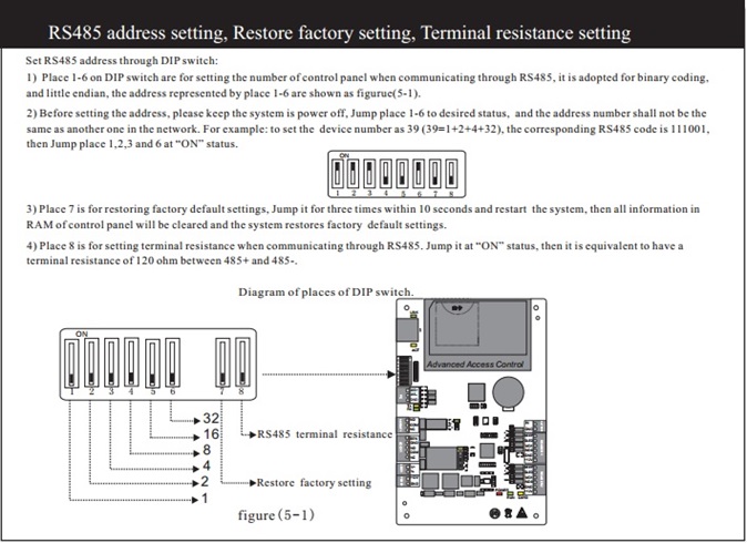
- Port (RS-485) – The serial port used on the PC running the driver that will be used to communicate to the controller.
- Baud Rate (RS-485) – Select the baud rate (data transmission rate) that will be used to communicate between the driver and the controller.
- IP Address (Ethernet) – IP address for the controller. The IP address field will automatically be populated if the controller was added using the Auto-Setup feature. To modify the IP address, type the IP value in the text box.
- Subnet Mask (Ethernet) – Subnet mask of the controller, used to connect via IP.
- Default Gateway (Ethernet) – Default Gateway of the controller, used to connect via IP.
- Last 3 Digits of MAC – This is the last 3 digits of the MAC address of the access control panel.
- InterLock– Configure whether or not to enable InterLocking. InterLocking prevents more than 1 door from unlocking for the controller.
- Anti-Passback– Configure IN and OUT readers and determine the properties for passback.
- Password– SCP password, set only when the controller has dip switch 8 to the on position. (Note: This Does not apply to ACP.)
- Function– Choose between Normal Access Control or Turnstile Access Control for the controller.
- Daylight_Savings– This property will enable / disable the observance of daylight savings in the controller’s internal clock. To modify the Daylight_Savings property, click on the drop down arrow to the right of the Daylight_Savings tag and select the Daylight_Savings option the controller should follow.
- GMT_Offset– Allows the controller to operate in different time zones from the server. To configure the GMT_Offset click on the drop down arrow to the right of the GMT_Offset tag and select correct GMT_Offset for the controller’s location.
- Report Aux Input– When set to ‘False’ this property will mask ALL Aux Inputs.