Axis A1001- Setup Guide
Considerations Prior to Setup
Please note the following considerations prior to setting up your A1001 controller.
- Is this a new or existing site?
- If this is an existing site, do you wish to import previously input user data (personnel records including name, last name, and card number) from the Axis Entry manager into Symphony AC. If so, you will need to set up the A1001 using the Help Wizard rather than the following manual instructions.
Note: The Help Wizard can also be used for new sites that do not require an import. To access the Help Wizard, launch Symphony AC and click Help to bring up the popup menu. Click on “Help Wizard” to launch the Help Wizard. Note: Files should NOT be manually placed in the Symphony AC/Downloads folder. This folder is specifically used by Symphony AC to download to the controllers. Additional files in this folder may cause downloads to the controller to slow down or download repeatedly. Prerequisites: Please ensure that you have the following:
- You MUST be on the most current version of Symphony AC
- Axis A1001 most current firmware available through Senstar
Obtaining the Axis A1001 Firmware File: The current Axis A1001 can be obtained at http://www.Senstar.net/downloads/axis.bin The A1001 firmware must be named “Axis.bin”. Once you have downloaded the A1001 firmware file, place the file into the Symphony AC Server’s “Data” folder. Typically, the “Data” folder is found in C:/Program Files(x86)\Symphony AC\ by default, but may change depending on where Symphony AC has been installed. Note: Senstar recommends simultaneously performing firmware updates to a maximum of five (5) controllers at once.
Setting Up the Axis A1001
For complete setup instructions, including how to wire and configure the Axis A1001, please consult the Axis A1001 User Manual, which can be located at: http://www.axis.com/files/manuals/um_a1001_1588954_en_1604.pdf I. Connect the A1001 Panel to the Network via LAN. Note: You must have PoE and Ethernet connected. As an alternative to PoE, you can use the AC Adapter. II. Initialize the A1001 Network Door Controller A. Obtaining the IP Address and IP Address Settings
- Enter the IP Address of the A1001 Network Door Controller in any web browser to access the Axis Entry Manager. Note your Firmware version. (See Figure 1)
Figure 1: 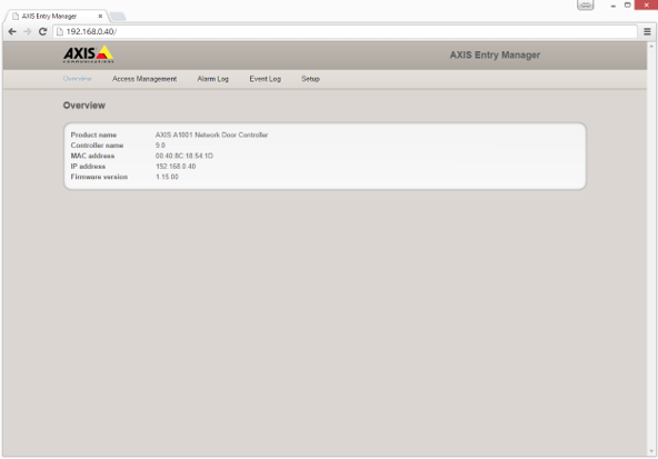
In the event that you do not have or know the IP address, please use one of the following options to obtain the IP Address: a. Default IP address: The A1001 is designed for use on an Ethernet network and requires an IP address for access. Most networks have a DHCP server that automatically assigns IP addresses to connected devices. If your network does NOT have a DHCP server, the Axis product will use 192.168.0.90 as the default IP address. b. To find the IP address, download and use the Axis IP Utility: http://www.axis.com/us/en/support/downloads/axis-ip-utility Note: If you have more than one controller, match the serial number to the controller to determine the proper IP address. After locating the IP address, enter the IP address into a web browser. A username and password will be required. By default, the username is root and the password is pass.
- If prompted, set the password. The default username is “root” and the default password is “pass”.
- Click the setup tab on the top right. Click “Additional Controller Configuration.” (See Figure 2)
Figure 2: 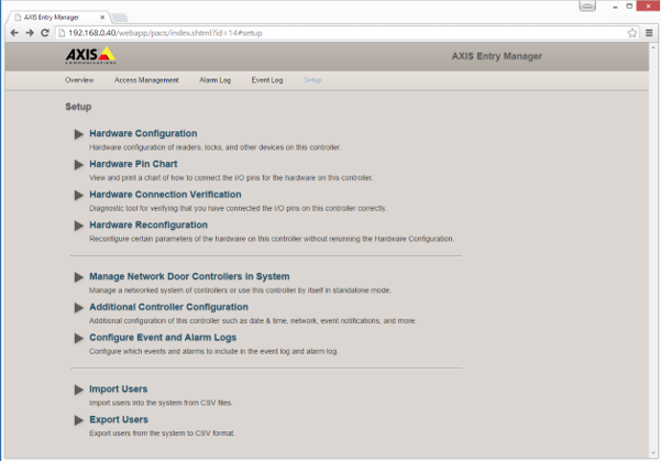
- Under “System Options,” click on Network. This will open the “Basic TCP/IP Settings” menu to configure the Basic Network settings.
- In the IP Address Configuration options:
Ensure that you set a static IP address by selecting “Use the following IP address” and enter your IP Settings.
- In the Services options:
Leave default settings in all fields. Click the “Save” button to finish setting up your static IP.
Figure 3: 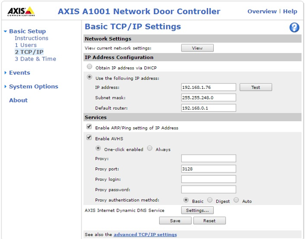
III. Setting Up the A1001 Within Symphony AC
- Launch Symphony AC and navigate to the Hardware Manager module. Unlock the module by clicking the lock in the command toolbar. Right click in the hardware tree and select “Edit” to display the “Add Driver” command from the popup menu. Click on “Add Driver” to view the “Add a New Driver” popup menu. (See Figure 4)
Figure 4: 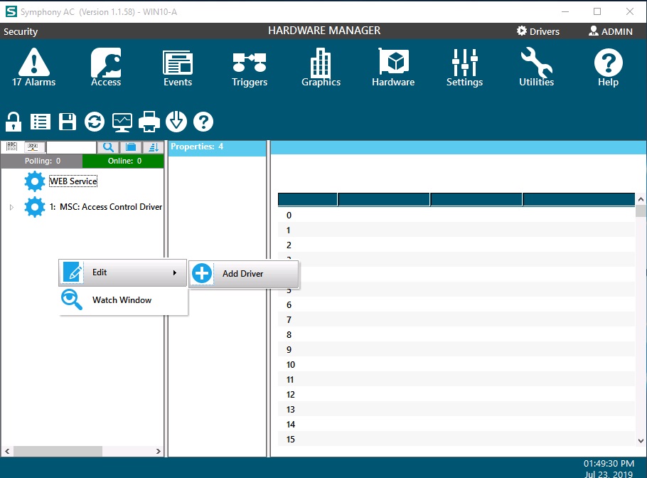
- From the “New Driver” popup menu, click on the “Access Control Drivers” category. Select the “Axis Access Control” driver. Click the OK (See Figure 5)
Figure 5: 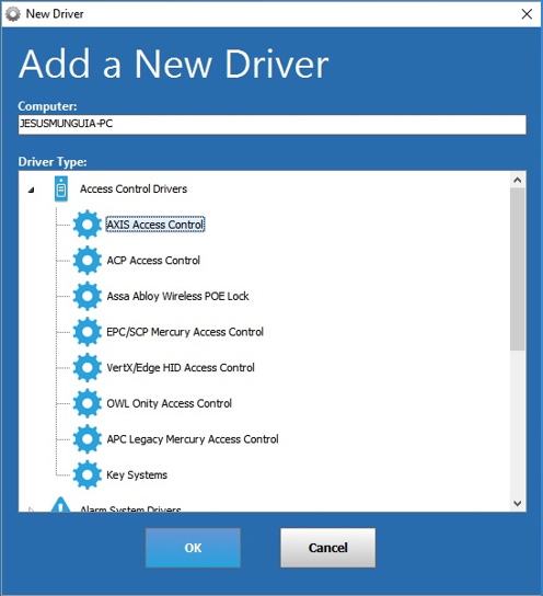
- Set the “Service username” and “Service Password” for the Driver. This is typically a local Windows user account that will be used to run the driver as a Windows Service. Click Save. (See Figure 6)
Note: The “Service User” needs to have rights to run Windows services. Usually, an Admin account will have the rights. If using a domain account, enter the full name. In the example below, the full name would be: (Senstar\JesusM).
Figure 6: 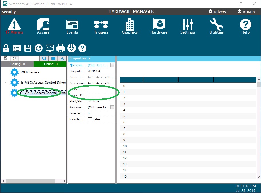
- Select the AXIS driver from the hardware tree and right click on it to bring up the popup menu. Select “Edit” and then “Add Controller.” (See Figure 7)
Figure 7: 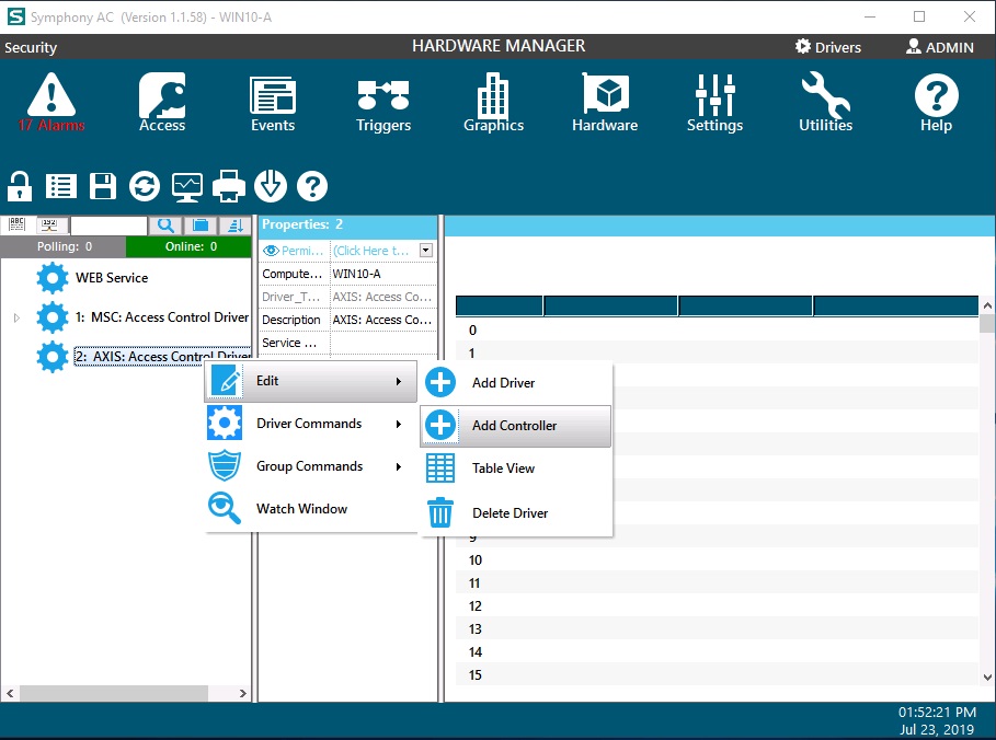
- There are two ways to add a controller. Controller(s) can be added manually one at a time or you can scan the network and add controllers.
a. To scan the network to add controllers, use auto setup and check the box next to the controller with the proper IP address that you wish to add.
- Note: More than one controller can be added simultaneously using the Auto Setup tool.
- Note: If using the auto setup tool, controllers can be viewed in the auto setup tool if they are in the same subnet. If you scan for the controllers with the auto setup tool but cannot see the controller, it is likely that the controller's IP address is set out of the server's reach because they are not on the same subnet. If this is the case, you will have to add the controller manually.
OR In the alternative, you can manually add controllers by using the manual setup. Select the controller type (here, Axis A1001 Network Door Controller). Select the Controller Address from the drop down menu and the Controller Group from the drop down menu. b. Click the “OK” button below to continue. (See Figure 8) Figure 8: 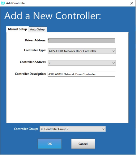
- Expand the hardware tree and select the newly added controller. In the properties box below the hardware tree, enter the correct “Password” for the controller. In the same properties box, enter the correct “IP Address.” (See Figure 9)
Note: If you used the auto setup feature to add the controller, you will NOT need to manually add the IP address. Figure 9: 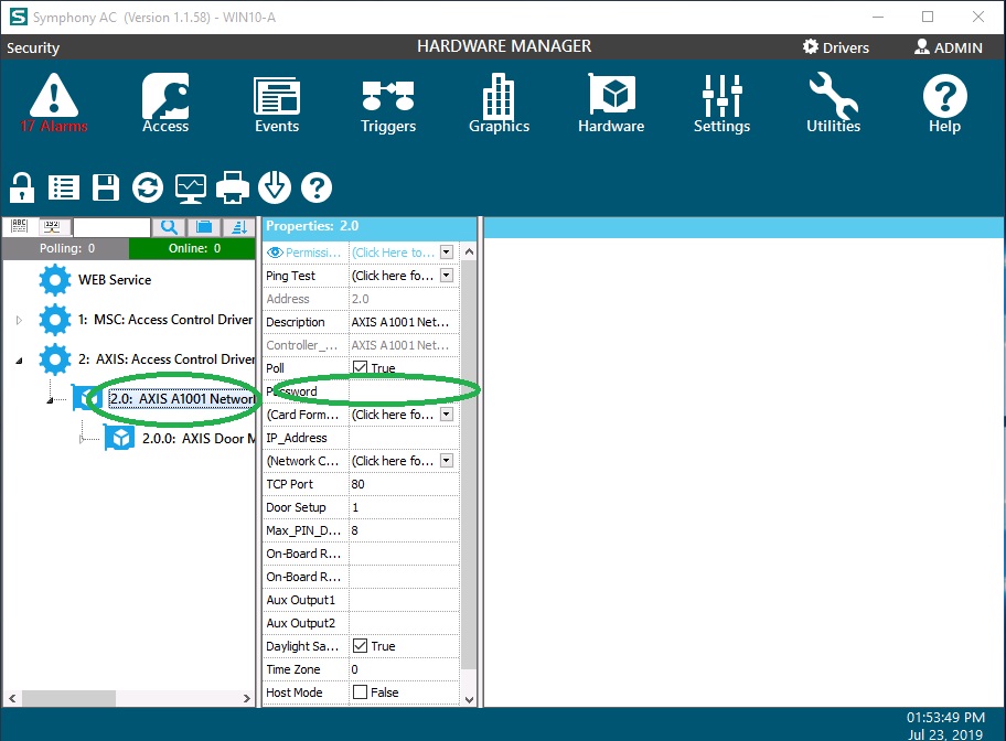
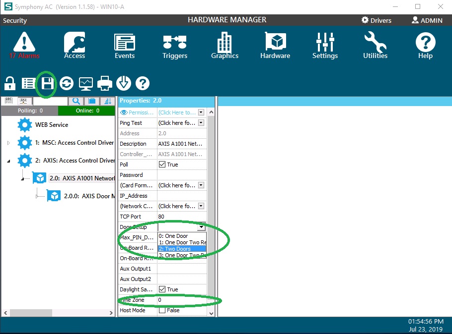
- In the properties box, select the “Door Setup” from the drop down menu with choices of One Door, One Door Two Readers, or Two Doors. (See Figure 10). Select a proper Time Zone and click the Save button. Figure 10:
- Starting the driver: Select the Driver in the hardware tree, right click on the driver, and select the “Start Driver” item from the “Driver Commands” menu. (See Figure 11)
Figure 11: 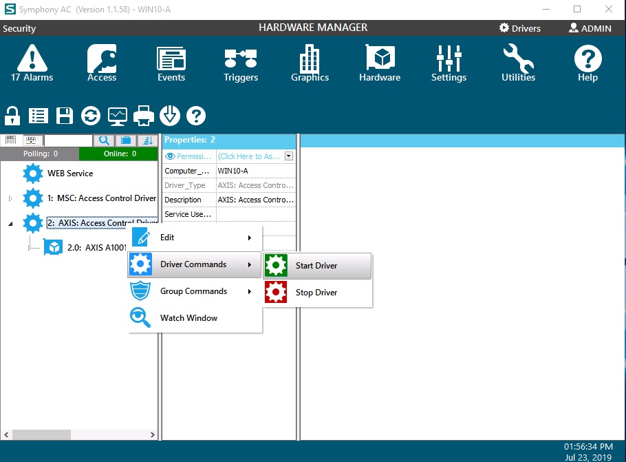
- Once the driver starts, a green box showing “AXI” will appear in the Information Window in the top right of the application. The Driver Status Screen should display “Running” in a green box along with the Time Date of the Driver, the Driver Version, and the DLL Version. The A1001 should show a status of Online in the top right.
- Once the A1001 is online, synchronize the Date and Time. Select the controller, right click, and select “Controller Commands” and then select “Set Date and Time.” When successful, the Controller Status screen should appear with a green “Online” status. (See Figure 13)
Figure 13: 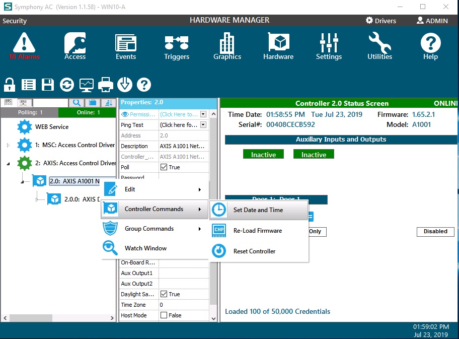
- Firmware Upgrade: Next, you will have to upgrade the firmware if you do NOT have the latest firmware. if you already have the latest A1001 firmware, you may skip the firmware upgrade.
a. Login to Symphony AC from any Client workstation with an Admin operator account.
b. Navigate to the Hardware manager module and unlock the module by clicking on the lock/unlock command. (See Figure 14)
Figure 14: 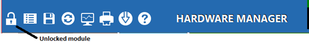
c. In the hardware tree, expand the Axis Driver and locate the Axis A1001 controller that you wish to update. Right click on the Axis A1001 controller, select Controller Commands and click Re-Load Firmware. (See Figure 15)
Figure 15: 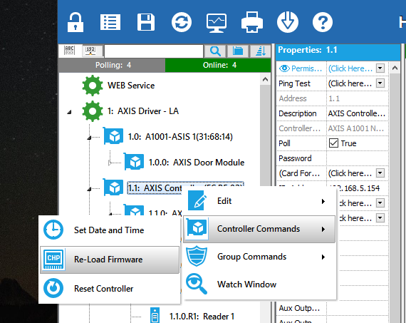
d. A "Re-Load Firmware warning message box will be displayed. Click Yes. (See Figure 16)
Figure 16: 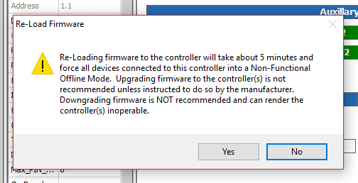
e. After you have initiated the Re-Load Firmware process within Symphony AC, there will be no additional messages to indicate that the firmware process is underway. After you have initiated the Re-load Firmware process, the A1001 controller will appear as Offline in Symphony AC, indicating that the firmware upgrade is in process. Please wait at least five (5) minutes before attempting to use the controller in any way.
Note: It is essential to ensure that the network to the A1001 and the power to the A1001 stay connected during the firmware download process. Otherwise, the controller will not function.
f. When the A1001 firmware has been successfully updated, the controller will come back online within Symphony AC. To verify that the firmware has been successfully updated, check the firmware version in the Controller Status Screen for the A1001 controller. (See Figure 17)
Figure 17: 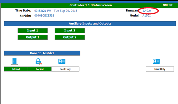
12. Resetting the Controller to Factory Default Settings:
WARNING: Resetting the controller to factory default settings will clear the panel of all data other than the controller’s IP address. Senstar highly recommends resetting every controller to factory default settings to ensure that Symphony AC can completely take over, as certain commands within the controller may sometimes conflict with commands in Symphony AC. To reset the controller to factory default settings, please follow the steps below:
a. Return to the Axis Entry Manager by entering the IP address of the controller in a web browser. Click “Setup” and select “Additional Controller Configuration.”
b. Under “System Options,” click on Maintenance then click “Restore” to reset all parameters except the IP parameters to the original factory settings. (See Figure 18)
Figure 18: 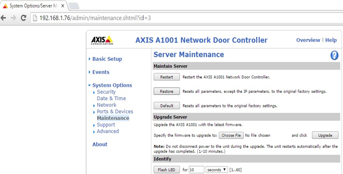
c. A popup message will ask you to confirm as such. Click OK to the popup message. (See Figure 19)
Figure 19: 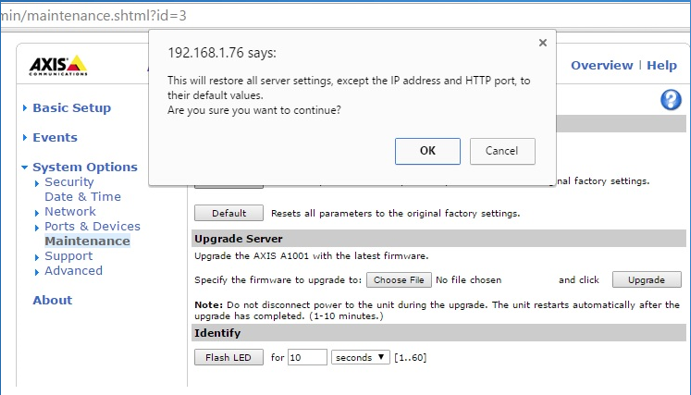
d. Once the Reset process is completed, you will be presented with the login window to enter a Password for root. Type in a password and remember to note the username and password, as these same credentials will be needed in Symphony AC. By default, the username is “root” and the password is “pass”. (See Figure 20)
Figure 20: 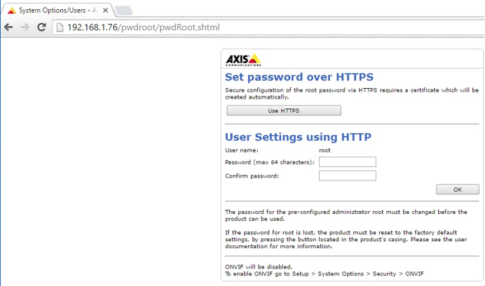
e. After typing in a password, click OK. (See Figure 21)
Figure 21: 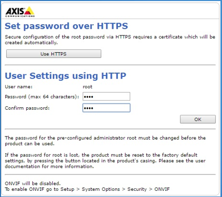
f. Type in the saved Credentials and click Log In to validate. Once confirmed, you can close your A1001 setting windows. The panel has been reset to factory default settings and is ready for Symphony AC to take over. (See Figure 22)
Figure 22: 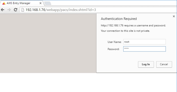
13. Once you are ready to download to the controller(s), click on the Download button located on the command toolbar. Ensure that all Database items EXCEPT Personnel Records (Controllers and Devices, Access Levels, Time Schedules, and Holidays) are checked. Select the A1001 controller to download to. To initiate a download to the selected controller(s), click on the “Begin Download” button. Once the Database items are downloaded, download the Personnel Records to the controller(s) by the same process. (See Figure 23)
Figure 23: 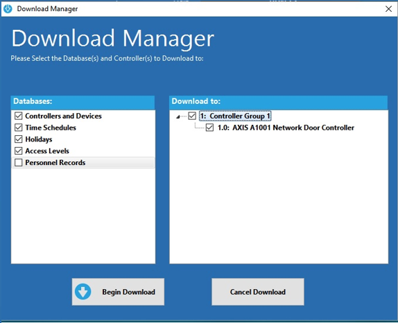
14. Expand the hardware tree and select the door. Set the properties for the door(s) and click on the Save command from the toolbar.
15. Right click on a door to test the Unlock/Lock commands. Events should now appear in real-time on the Event Manager.
IV. A1001 Controller Properties Within Symphony AC
After you successfully add the A1001 controller to Symphony AC, you will have the ability to modify controller properties. Below is a list of the controller properties for the A1001 controller within Symphony AC.
- Ping Test: Performs Ping test to controller to verify connectivity in network
- Address: A controller’s address number is used to identify a specific controller.
- Description: Description/Name of Controller. This can be changed to identify an individual controller. For example, a controller can be identified as “Main Doors”.
- Controller_Type: Identifies Model of Controller. This cannot be modified.
- Poll: This tells Symphony AC whether or not to establish communication with controller. When the box is checked, Symphony AC is communicating with the controller and vice versa.
- Password: This is the password used to access controller. Typically, it is the same password used for entry manager.
- Card Formats: Defines what card formats will be used with the readers connected to this controller.
- IP_Address: Displays each controller’s IP Address
- (Network Configuration): Click here to open and use entry manager to change the IP settings.
- (Access Management): Click Here to open and use entry manager to view access management.
- TCP Port: Allows configuration of the TCP port.
- Door Setup: Select the appropriate configuration you wish to use with this controller from the following:
- 0: One Door
- 1: One Door 2 Readers
- 2: Two Doors
- Max_Pin Digits: Enter the Maximum Digits for a user’s PIN number. The maximum digits must be greater than or equal to 4, as the user must always have at least four (4) digits for a user’s PIN number.
- On-Board Relay: Assign On-Board Relay to a door from the following options:
- 0: No Assigned Door
- 1: Door 1
- 2: Door 2
- On-Board Relay Locked: Select the “normal” status of the relay:
- 0: Relay Closed
- 1: Relay Opened
- Aux Output1 and Aux Output2: Assign or link Aux Relays to a door from the following options:
- 0: No Linking Assigned
- 1: Activate on Door 1 Alarm
- 2: Activate in Door 2 Alarm
Note: Aux relays must be set up to be outputs through Entry Manager. Aux Relays are only activated on door alarms.
- Daylight Saving: Enable or disable Daylight Savings Time. The “True” value indicates that Daylight Savings Time is enabled and the “False” value indicates that Daylight Savings Time is disabled.
- Time Zone: Apply a specific time zone to a controller (usually corresponding with its location).
- Host Mode: Host mode allows access control decisions to be made by the driver rather than the controller. When there are a large number of credentials, the user may want to enable host mode. To enable host mode, check the box so that the value shows as “True”.
Note: When Using Host Mode Controller MUST be communicating with Symphony AC at ALL times.